Saturday, 28 April 2018

Motors

Motors

Servos


DC Motors


https://embetronicx.com/tutorials/tech_devices/l293d-motor-driver-working/
https://github.com/espressif/esp-idf/tree/master/examples/peripherals/mcpwm/mcpwm_brushed_dc_control


http://www.instructables.com/id/DIY-Motor-Driver-With-ESP32-Controller/

Resistors

Resistors


Ohms Law

V=I x R
V = voltage (Volts)
I = current (Amps)
R = resistor value (Ohm)

The ESP32 uses 3.3V logic
The current should be less than 25mA  (.025A)
For a switch (resistance about 0 Ohm)
R = 3.3V / .025A = 132 Ohm

LED (~ 2V if it's a old fashioned red, yellow, green, orange one)

V = 3.3V - 2V = 1.3V
I = At most 25 mA
R = 1.3V / 0.25A = 52 Ohm

But that would be really bright and use up our battery quickly
(Power = VI)  So we'll use something bigger eg 1k or 2k.


You can use a multimeter to work out a value of  a resistor.
You can also read the colour bars:

About resistors and a colour chart


http://www.resistorguide.com/resistor-color-code/

Resistor Calculator  - put in the colours and it will tell you the value

http://resistor.cherryjourney.pt/


Hardware

Hardware

Output
  • Motors
    • Servos
    • DC Motors
  • LEDs
    • On-board LED
    • Standard LEDs red, yellow, green 
    • neopixels - multicolours
  • Infrared transmitter
  • Piezo sounder
Input
  • Push Buttons
  • Capacative touch
  • photoresistor
  • infrared receiver
  • Varistor
  • Pir movement sensor

Transistors
https://learn.sparkfun.com/tutorials/transistors

Software Setup

Notebook Setup


Linux - Debian - Gnome

Alt-TAB to swap between different programs
Alt-` to swap between winows of the same type (` is above the left TAB)


Arduino IDE - edit code and program ESP32
Fritzing - Breadboard wiring

ESP32

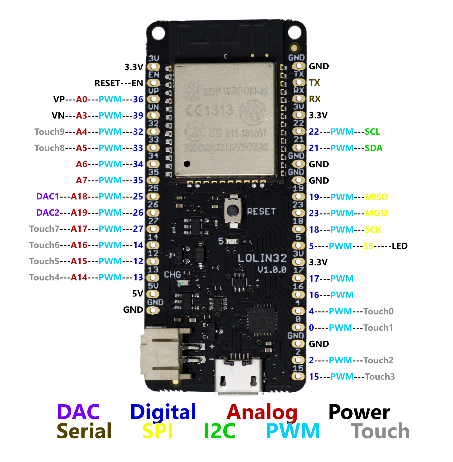
WEMOS Lolin32 ESP32 based Microcontroller


Microcontroller - a CPU with Hardware I/O and WIFI
- You can turn things on and off with it
- You can send it signals
- You can talk to it from a phone or a computer
- They can talk to each other


Short side
Pin 1 = 3.3 V (that will be either battery or from usb (dropped to 3.3)
Pin 2 = EN
Pin 3 = VP - A0  - PWM - I36 (Input Only)
Pin 4 = VN  - A3 - PWM - I39 (Input Only)
Pin 5 = Touch 9  - A4 - PWM IO32
Pin 6  = Touch 8 - A5 - PWM IO33
Pin 7  = A6  PWM I34 (Input only)
Pin 8 = A7 PWM I35  (Input Only)
Pin 9 = DAC1 A18 PWM IO25
Pin 10 = DAC2 A19 PWM IO26
Pin 11 = TOUCH 7 - A17 PWM IO27
Pin 12 = TOUCH 6 A16 PWM IO14
Pin 13 = TOUCH 5 A15 PWM IO12
Pin 14 = TOUCH 4 A14 PWM IO13
Pin 15 = +5 V
Pin 16 = GND

Long Side
Pin 1 = GND
Pin 2  = TX
Pin 3 = RX
Pin 4  =3.3 V
Pin 5 = IO22 PWM SCL (I2C)
Pin 6 = IO23 PWM SDA (I2C)
Pin 7 = GND
Pin 8  = GND
Pin 9 = IO19 PWM MISO (SPI)
Pin 10 = IO23 PWM MOSI (SPI)
Pin 11 = IO18 SCK (SPI)
Pin 12 = IO5 = PWM S5 (SPI) On board LED (Pulled up - inverted) = GPIO2
Pin 13 = 3.3V
Pin 14 = IO17 PWM
Pin 15 = IO16 PWM
Pin 16 = IO4 PWM Touch 0
Pin 17 = IO0 PWM (Touch 1 disabled because the reset button is attached)
Pin 18 = GND
Pin 19  = IO2 PWM Touch 2
Pin 20 = IO15 Touch 3


Useful Links

https://wiki.wemos.cc/products:lolin32:lolin32

ESP32Village Welcome

Welcome to the ESP32 Village Project

What do you want to do?